
Engineering resource · Electrical insulation
How to Choose PET Film Thickness for Electrical Insulation Parts
Choose PET film thickness by checking minimum film thickness against electrical and service requirements, and the maximum installed stack against assembly space.
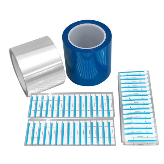
Choose PET film thickness by assessing the specified minimum film thickness against the electrical and service requirements, then checking the maximum permanent layer stack against the available assembly space. Confirm the PET grade first, and evaluate bends, cutouts, and contact edges in the actual part geometry before approving the construction.
These checks answer different questions. A thicker film may still create an interference or an unsuitable bend, while a thinner film that fits has not yet demonstrated adequate insulation. The useful outcome is a set of candidates with clear reasons to accept, reject, or test each one.
Check the PET grade for heat, moisture, and shrinkage
Thickness comparison starts within the material and construction that the project permits. If a drawing or an approved insulation system specifies a grade, minimum thickness, or layer arrangement, retain those conditions when evaluating alternatives. The label “PET” does not identify all of them. [3]
Consider heat and moisture together. DuPont Teijin Films' physical-thermal bulletin describes hydrolysis and embrittlement of Mylar under hot, humid conditions. Its discussion of shrinkage also explains that heating can release strains introduced during film manufacture or processing. For a shaped barrier, dimensional change can affect the outline and its position relative to nearby features. [1]
Use the candidate grade's exposure and shrinkage data to decide whether it remains suitable for the assembly. A temperature used in a short laboratory test is not, by itself, a continuous operating rating. Adding thickness also does not establish that the grade will retain the required flexibility after exposure. [3, 7]
Where material recognition is required, read the complete record for the exact grade, color, thickness, and property. The UL record for Melinex 238(b), for example, contains thickness-dependent entries and a substantive footnote limiting its flame-class statement. Treating all entries as one unrestricted material rating would lose an important condition of selection. [2]
Use thickness-specific PET data to screen electrical requirements
Working voltage describes service stress; breakdown voltage records specimen failure in a defined test. Dielectric strength is the associated thickness-normalized field, often in kV/mm. Keep the candidate's grade, thickness, and conditions attached to those values when comparing them with the project's electrical requirements. [6]
Melinex 238's May 1, 2024 data sheet gives these typical values. The nominal metric labels follow the manufacturer's electrical-insulation brochure and are not measured thicknesses or tolerance limits. [4, 5]
Table 1 Reported typical breakdown values for Melinex 238 [4, 5]
| Manufacturer gauge designation | Nominal metric label | Typical breakdown voltage |
|---|---|---|
| 500 | 125 µm | 16 kV |
| 760 | 190 µm | 19 kV |
| 1000 | 250 µm | 23 kV |
| 1400 | 350 µm | 26 kV |
Swipe horizontally to view all columns.
Test conditions are 50 Hz, 500 V/s, and 6.3 mm electrodes. Temperature, surrounding medium, conditioning, and sample distribution are not reported. Melinex 238 is an electrical-machine grade, used here to interpret data rather than recommend a material for every barrier. [4]
The nominal thickness doubles from 125 µm to 250 µm, while typical breakdown voltage changes from 16 kV to 23 kV, about 44% higher. These are reported material results, not a working-voltage rating or specification minimum. [4, 7]
Next, identify the thickness limit that the design actually relies on. A nominal thickness or a typical actual-thickness entry does not define the permitted minimum. That minimum must come from the controlled material or part specification and the applicable qualification basis. Dividing working voltage by a typical dielectric-strength value does not establish an acceptable minimum PET thickness. [3, 6, 7]
Review AC and DC evidence in the form reported. ASTM D149-25's public scope addresses commercial-power-frequency testing and excludes determining direct-voltage dielectric strength. A required withstand test needs its own stated conditions and acceptance basis; a typical breakdown row does not supply them. [6]
Check the maximum installed stack against the minimum available space
Assembly fit concerns the layers that remain in the equipment. Define them before adding thicknesses. The same supplied part can have a film thickness, a permanent installed thickness, and a delivery thickness that includes a removable liner.
Table 2 Keep the thickness objects separate [8, 9]
| Layer or object | How to treat its thickness |
|---|---|
| PET film | Identify the film's own thickness limits and relevant material data. |
| Adhesive layer | Include it in the permanent stack when it remains installed. Do not automatically count it as equivalent PET insulation. |
| Other retained layers | Include each defined layer in the installed construction. |
| Removable release liner | Exclude it from this installed-stack calculation only when it is removed before installation. |
Swipe horizontally to view all columns.
A real product illustrates the distinction: 3M's November 2024 data sheet lists a nominal 0.025 mm polyester backing for 1350F-1 and a nominal 0.064 mm total tape thickness. The latter is not 0.064 mm of PET. The table is described as representative or typical, so its entries should not be turned into general film or adhesive purchasing limits. [8]
Worked example of a PET and adhesive stack
Consider a hypothetical flat assembly with 0.160 mm of minimum available space, already allowing for the mating parts' dimensional tolerances. Compare two PET candidates, each with one permanent adhesive layer. For this example only, assume a PET thickness tolerance of ±0.010 mm and an adhesive thickness of 0.025 ± 0.005 mm. The release liner is removed, no other layer remains, and no reduction from adhesive compression is credited.
All values in this example are assumed inputs. They are not manufacturer tolerances, TC specifications, test results, or a standard's acceptance limits.
Table 3 Nominal fit and maximum-stack fit can give different answers
| Candidate | PET nominal thickness | Nominal installed stack | Maximum installed stack | Result against 0.160 mm |
|---|---|---|---|---|
| A | 0.100 mm | 0.125 mm | 0.140 mm | 0.020 mm remaining |
| B | 0.125 mm | 0.150 mm | 0.165 mm | 0.005 mm interference |
Swipe horizontally to view all columns.
Both nominal stacks fit. At its assumed upper limits, however, candidate B combines 0.135 mm of PET with 0.030 mm of adhesive, producing a 0.165 mm stack. It therefore fails this dimensional screen. Candidate A remains within the available space under the same assumptions.
Candidate A's assumed PET range is 0.090 to 0.110 mm. Its electrical and service evidence still needs to cover the intended construction and permitted film thickness. The 0.020 mm of remaining space is dimensional headroom, not an electrical clearance requirement or evidence of insulation safety. The Melinex values in Table 1 do not qualify either hypothetical candidate.
For an actual part, use the approved final-laminate upper limit or a consistent calculation from its constituent layers. Do not add the same tolerance again after it is already included in an upper-limit value. If the construction bends, overlaps, or changes thickness under the assembly load, evaluate that geometry and measurement state explicitly rather than relying on this flat-stack example.
Treat multiple layers as a different construction
Equal nominal total thickness does not establish electrical equivalence between one PET film and several films joined with adhesive. Each layer and interface belongs to the construction being evaluated. The original Mylar electrical bulletin reports that coatings can improve some properties, while other coatings or potting compounds can reduce performance. The direction and size of an untested adhesive's effect cannot be inferred from added thickness. [10]
Keep a multilayer option in consideration when the project permits it, but obtain evidence for that complete construction. Adding the separate films' breakdown voltages is not a qualification method. [4, 9]
Match PET thickness to bends, cutouts, and contact edges
In small-strain, linear elastic bending of a uniform strip, thickness changes bending stiffness. At the same neutral-axis curvature, the outer material's greater distance produces greater strain. A thicker candidate can therefore require more forming force and greater outer-film deformation to follow the same bend. [11]
This comparison holds material response, direction, width, temperature, and loading conditions comparable. It does not define a universal PET bend radius or cover creasing, repeated folding, or a laminate's neutral axis. Compare candidates in the actual bend and retention geometry, including both conformity and positioning needs. [11]
Local damage is a separate question. ASTM D1004 addresses the force to initiate a tear in a defined specimen, while ASTM D1922 addresses propagation after a tear has started. Their public guidance warns against simple cross-thickness scaling; D1922 also discusses the effect of film orientation. A tensile-strength value therefore cannot, by itself, answer whether a narrow tab or cutout will survive the assembly operation. [12, 13]
If damage begins at a hole, slot, or contact edge, inspect that location, the film direction, and the permitted movement between the parts. Compare the candidates under the same relevant conditions before deciding whether thickness or the interface needs to change. For a film that must bend after environmental exposure, include retained ductility in the assessment; the historical Mylar steam-exposure data illustrate why modulus and elongation must be distinguished. [1, 12, 13]
Specify the PET construction and validate the converted part
Put the chosen construction on the drawing in terms that both purchasing and inspection can use: the exact film grade, the film's thickness limits, the retained layer structure, and the relevant installed-stack limit. State the measurement condition when adhesive, liners, or assembly pressure could change what is being measured. This makes it possible to determine whether two quotations or samples describe the same proposed part.
Plan acceptance around what each check can establish. A dimensional check establishes the defined fit. Inspection at bends and cut features addresses the specified mechanical condition. Electrical and environmental acceptance must use the relevant material, part, or equipment requirements and the actual construction. A material recognition record and a raw-film result cannot approve the converted part or the complete equipment on their own. [3, 9]
The thickness decision is ready for prototype review when the candidate, its dimensional limits, and the remaining functional questions are explicit. For a PET part review with TC Precision Components, share the drawing, proposed layer stack, and the electrical and environmental requirements that still govern the decision.
Sources and technical references
[1] DuPont Teijin Films — Mylar Physical-Thermal Properties.
H-37232-3, June 2003. Historical original bulletin; dimensional stability, hydrolytic stability and Figures 7–9. Used for qualitative mechanisms, not current product limits. Source
[2] UL Solutions — Melinex 238(b), E93687.
Record last revised August 22, 2026. Public material record including thickness entries and footnote (b). Source
[3] UL — Yellow Card for Plastics.
2016 public brochure. Recognition conditions and property interpretation; not a project-specific approval. Source
[4] Mylar Specialty Films — Melinex 238 Technical Datasheet.
Revised May 1, 2024. Typical properties and stated test conditions; not specification limits. Source
[5] Mylar Specialty Films — Polyester Films for Electrical Insulation.
Public brochure; revision date not identified. Page 3 manufacturer gauge and nominal metric labels for Melinex 238. Source
[6] ASTM International — ASTM D149-25.
2025 edition. Public Significance and Use and Scope only; paid full text not used. Source
[7] Mylar Specialty Films — Mylar A 500 Micron Made in UK Technical Datasheet.
Revised October 1, 2024. Typical actual thickness and the data-use limitation; not a thickness recommendation. Source
[8] 3M — Polyester Film Electrical Tape 1350F-1 and 1350F-2 with Acrylic Adhesive.
November 2024, Rev D. Page 1 backing and total thickness; table data described as representative or typical. Source
[9] ASTM International — ASTM D2305-18.
2018 edition. Public conditioning and scope statements, including homogeneous film versus combinations; paid full text not used. Source
[10] DuPont Teijin Films — Mylar Electrical Properties.
Revised April 3, 2017. Original bulletin section 8 on coatings and potting compounds; historical document. Source
[11] MIT OpenCourseWare — Transverse Loading of Slender Structural Elements Beam Theory.
Fall 2021 course. Pages 4–5 and 14–17; bounded elastic-bending explanation, not a PET qualification. Source
[12] ASTM International — ASTM D1004-21.
2021 edition. Public Significance and Use and Scope on initial tearing and comparison limits; paid full text not used. Source
[13] ASTM International — ASTM D1922-23.
2023 edition. Public Significance and Use and Scope on propagation tearing and orientation; paid full text not used. Source