
Engineering resource · Quality, tolerances & DFM
Die-Cut Part Drawing Checklist: Critical Dimensions, Tolerances & Material Stack-Up
Define critical dimensions, tolerances, material stack-up, liner conditions and measurement requirements before RFQ, prototype review and production release.
A die-cut part drawing should tell the supplier more than what shape to cut. For an electronic or industrial functional component, it should identify which features control assembly fit, how their tolerances are defined, which material and adhesive layers remain in the installed part, and how the finished part will be measured. Otherwise, two suppliers may quote the same outline while making different assumptions about hole locations, laminate thickness, liner retention, or inspection.
You do not need a production-ready CAD package to start a discussion. A sketch, a reference part, or a preliminary drawing can be enough to identify the open questions. Before prototype results can be meaningfully evaluated, however, the part configuration and the purpose of that prototype need to be clear. This guide shows what to define at each stage, using one deliberately hypothetical die-cut cushion/spacer as a running example.
Define the Part, Its Function, and the Controlling Revision
Start with the interface that the component must fit. A film insulator that must cover an exposed conductive area, a compressible spacer positioned between two housing surfaces, and an adhesive-backed pad located by mounting holes may share a similar outline. Their critical dimensions are not necessarily the same. The function identifies which edges, holes, or contact surfaces must be controlled; the drawing then communicates those relationships.
Give the part an identifier and revision that can follow the work from quotation to prototype review. Show the unit system, the relevant view and orientation, and which drawing or CAD file governs if several files are supplied. When a material stack-up table or assembly sketch is in a separate file, identify its revision too. If the PDF shows one hole location and the CAD file shows another, the supplier needs a controlled decision about which is current—not an assumption based on the latest file timestamp.
Define what the part contacts and how it is oriented. For an adhesive-backed pad, for example, the substrate-facing adhesive side matters as much as the 2D outline. If the part is asymmetric or handed, show that explicitly. An assembly image or mating-component drawing can clarify a locating requirement that is hard to communicate by dimensions alone.
At the initial inquiry stage, missing information is acceptable if it is visible. Mark the material choice, application gap, or critical fit as an open item rather than silently treating a preliminary concept as a released specification. Engineering drawing practices and revision control are covered by the ASME Y14 family, but the standard and document hierarchy applicable to a particular project must be established by that project [1].
Dimension the Features That Actually Control Assembly Fit
The key question is not simply, “Have all features been dimensioned?” It is, “Can another engineer locate the features that matter relative to the same functional references?” An accurately sized hole can still fail to line up with a mating pin if its center location is ambiguous. Conversely, adding dimensions that do not control fit may introduce conflicting requirements when two values describe the same geometric relationship independently.
Consider HYP-DC-01, Revision A, a hypothetical flat adhesive-backed cushion/spacer. It is not a customer drawing or a demonstrated manufacturing capability. All values below are illustrative nominal dimensions in millimeters, with the lower-left corner of the rectangle used only as a simple coordinate reference—not as a formally specified GD&T datum system.
| Feature | Illustrative nominal definition | What the reader must still decide |
|---|---|---|
| Outside profile | 48.0 × 28.0 mm rectangle | Which outside edges locate the part or constrain clearance? |
| Left hole, H1 | Ø4.0 mm; center (8.0, 14.0) | Does its position control alignment with an assembly feature? |
| Right hole, H2 | Ø4.0 mm; center (40.0, 14.0) | Is the hole pattern located from the outside profile or from a mating feature? |
| Central slot, S1 | Horizontal obround, 8.0 mm overall length × 4.0 mm width; center (24.0, 14.0); end radius R2.0 mm | Which slot edges or position control clearance? |
| H1–H2 center spacing | 32.0 mm REF | Reference only here; do not assign a second independent tolerance without defining the controlling dimension scheme. |
Swipe horizontally to view all columns.
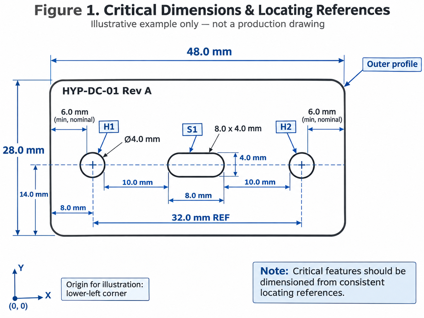
The geometry is internally consistent: the circular holes are 32.0 mm apart; each outer hole has a nominal 6.0 mm gap to its nearest short edge; and the closest nominal gap between either hole and the central slot is 10.0 mm. Those relationships are not minimum manufacturing limits or approved tolerances. They only make the hypothetical geometry traceable.
A note such as “two Ø4 holes, centered” does not convey the same information as defined hole-center locations from stated reference edges or assembly features. If the part locates against a housing edge, that edge-to-hole relationship may be the controlling one. If the mounting pins themselves establish position, the hole pattern and its relationship to those pins may matter more than an arbitrary outside edge. Choose the dimensioning scheme that reflects the actual assembly relationship, rather than automatically applying every available dimension.
Also inspect narrow webs and corner features. The nominal width of material left between a hole and an opening is the result of several feature locations and sizes, not an isolated dimension. A designer who needs a minimum remaining ligament must define what that minimum is and how variation in the neighboring features affects it. The values in the example do not establish manufacturability; they establish where a real fit or structural requirement would have to be specified.
ASME Y14.5 provides an established dimensioning-and-tolerancing framework [1]. It does not mean a simple die-cut drawing automatically needs a complete set of geometric tolerance symbols. The governing drawing convention and the necessary controls should match the project's assembly and inspection requirements.
Assign Tolerances by Function, Material, and Feature Type
A nominal dimension expresses the intended geometry. A tolerance defines the variation that can be accepted under an agreed measurement basis. Those are separate decisions, and they become especially important for flexible films, foams, elastomer sheets, and adhesive laminates.
Suppose the two holes in HYP-DC-01 are needed for assembly alignment while the outside profile merely requires clearance inside a housing. Giving the hole location and the outer profile the same inherited title-block tolerance would not, by itself, express those different functions. One requirement could be unnecessarily restrictive while another fails to protect the intended interface. That conclusion is about the logic of allocation, not about any universal numerical tolerance for die cutting.
| Requirement type | What it controls | What must be defined for a useful acceptance requirement |
|---|---|---|
| Outside profile | Part fit against an envelope or locating boundary | Controlled edges or contour, allowed deviation, and inspection state |
| Hole or slot size | Clearance or engagement with mating features | Defined feature size and its allowed limits |
| Hole/slot position | Alignment with a mating component | Position relative to the chosen functional references |
| Layer-to-layer registration | Alignment of adhesive, film, foam, openings, or exposed areas | Which layers must align and where registration matters |
| Permanent laminate thickness | Available assembly space before installation or loading | Included layers, liner status, tolerance basis, and measurement method |
Swipe horizontally to view all columns.
These categories should not be collapsed into a single “precision” number. Layer registration is not the same as the overall outline tolerance. A raw foam sheet's thickness tolerance is not automatically the tolerance of a converted, adhesive-backed part. The nominal die or tool geometry is also not necessarily identical to the dimensions measured on a relaxed, flexible finished component.
Material behavior explains part of the difference. A thin film may be sensitive to handling and support; a soft foam can deform under measurement contact; a laminated construction can add an alignment requirement between layers. For example, if adhesive must not extend into a clearance opening, the relationship between the adhesive cut and the foam opening may need its own registration requirement—even when the outer profile is acceptable. Small openings, closely spaced features, and narrow webs change what needs to be checked during a process review. None of these observations justifies assigning a blanket tolerance without examining the actual grade, geometry, cutting process, and inspection condition. Rogers, for example, publishes different material thickness-tolerance information for configurations within its PORON 4701-40 family; those figures are material-specific and must not be recast as a die-cut-part capability [2].
For a functional feature, work backward from the mating condition: identify the permissible positional or dimensional variation, decide which reference relationship expresses it, and then review whether the proposed material construction and converting route can be evaluated against that requirement. If a tolerance cannot yet be justified, label it as pending engineering review. Do not fill the drawing with an assumed ± value simply because a quotation is needed.
Document the Material Stack-Up and the Thickness You Mean
“Foam with double-sided adhesive, total thickness 1.2 mm” can describe more than one product. Does 1.2 mm include the adhesive? Does it include a carrier inside the tape? Is the release liner part of the quoted thickness? Is the stated thickness before the foam is compressed? These distinctions affect assembly clearance, how the part is cut, and which measurement can be used for acceptance.
Record the layer sequence from a stated viewing direction, the material identity and its revision where known, which side is exposed for bonding, and which layers are permanently retained. If only certain zones are adhesive-coated, that geometry belongs in the definition too. A layer table can be attached to the drawing; it does not all have to be crowded into the plan view.
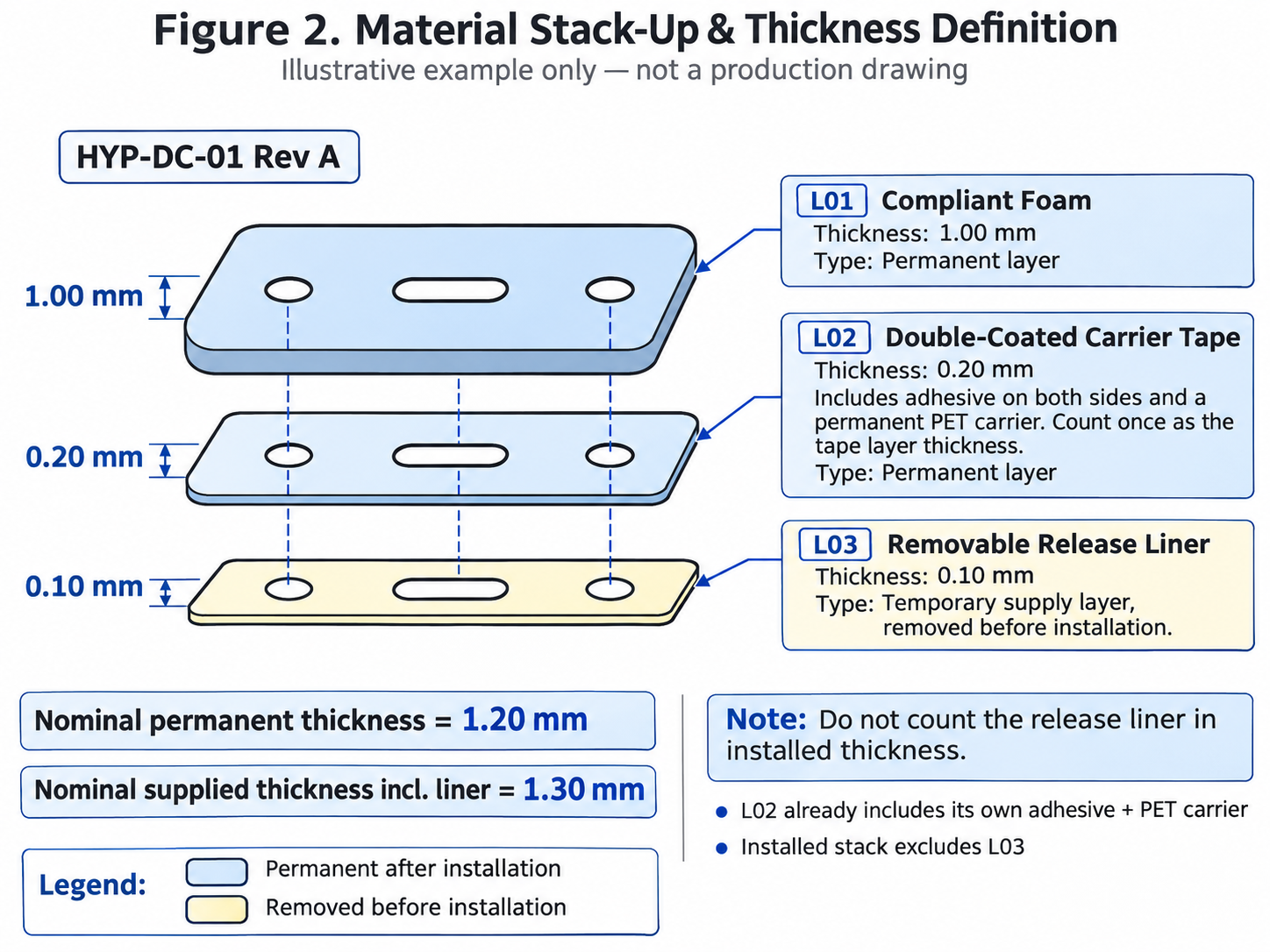
For HYP-DC-01, assume the following invented nominal construction, chosen to explain terminology rather than to represent a purchasable grade:
| Layer, top to bottom | Illustrative construction | Nominal thickness | Present after liner removal? |
|---|---|---|---|
| L01 | Compressible foam body; material grade not selected | 1.00 mm | Yes |
| L02 | One double-coated tape consisting internally of two adhesive coats and a permanent PET carrier | 0.20 mm total tape thickness | Yes |
| L03 | Separate removable release liner | 0.10 mm | No |
Swipe horizontally to view all columns.
The nominal permanent stack is 1.00 + 0.20 = 1.20 mm. The nominal as-supplied stack including the liner is 1.00 + 0.20 + 0.10 = 1.30 mm. These are arithmetic sums of hypothetical input values, not measured finished-part thicknesses, tolerance limits, or installed thickness guarantees. The 0.20 mm tape has already counted its internal adhesive coats and PET carrier; adding those again would double-count the tape construction.
The distinction is visible in real manufacturer data, although the hypothetical materials above are not identified as these grades. The September 2024 technical data sheet for 3M Double Coated Tape 9495LE separately lists typical adhesive coats of 0.071 mm and 0.086 mm with a 0.013 mm PET carrier, totaling 0.170 mm for the tape, and a 0.110 mm release liner [3]. The data sheet labels its values as typical or representative rather than specification limits. It therefore helps explain what a “tape total” means; it does not provide the dimensions or acceptance limits for HYP-DC-01.
Not all adhesive formats have the same construction. An adhesive transfer tape may lack a permanent carrier, whereas a double-coated carrier tape includes one. The material callout should describe the actual chosen construction rather than assuming that every double-sided adhesive contains a PET film. The liner should be identified separately when it will be removed before installation.
Material selection also needs an explicit approval rule. If an assembly has qualified an exact manufacturer grade and revision, retain that identification in the drawing and related specification. If alternatives are allowed, state that they may be proposed for evaluation, not that any item with the same thickness is interchangeable. The comparison may require construction, adhesive-to-substrate compatibility, compression behavior, operating environment, and the intended component or assembly test. If the grade is not yet decided, record the required function and the unresolved qualification criteria instead of manufacturing an approval by omission.
Mark Cut Boundaries, Adhesive Faces, and Delivery Form
Once the layer structure is clear, the next question is what the supplier is being asked to leave behind. For the example pad, the outside profile, H1/H2 holes, and S1 slot are intended to be cut through L01 and L02, while the underlying L03 liner remains continuous. The functional-layer waste around the outside and inside the holes and slot is to be removed. After liner removal at assembly, the finished pad has the specified openings.
This requested layer-by-layer result differs from punching through all layers. A fully severed liner can change handling, part presentation, and removal at the assembly station. A nominally correct part outline may still be unsuitable if the waste slugs remain in the openings or if the liner arrangement prevents the intended pick-and-place or manual installation sequence. tesa's published converting examples distinguish full punch-through and liner-related converting options, illustrating why these outcomes should be specified separately [4].
Do not confuse a functional requirement with a manufacturing instruction that has not been verified. “Cut L01 and L02; retain an unsevered L03” describes the desired outcome. It does not establish that a single die stroke will meet it, that the liner will have no marks, or that a chosen foam/tape/liner combination will strip cleanly. Acceptable liner scoring, tool selection, scrap-removal behavior, and production feasibility depend on the actual materials and the proposed process.
State the delivered form when it changes assembly use: loose individual pieces, parts arranged on sheets, or parts on a continuous liner are different outputs. Indicate orientation and presentation only to the extent required for correct use. A supplier can then evaluate the suitable conversion route while keeping the part's functional and delivery requirements distinct from the tooling method.
Define How Flexible Parts Will Be Measured and Accepted
For a rigid, unambiguous feature, two measurements may be straightforward to compare. On a flexible laminate, the reported number can depend on what is included in the specimen and how it is supported or loaded. In particular, the layer sum specified on paper is not necessarily the same as a thickness reading taken under contact pressure, and neither should be silently substituted for the assembled gap.
The HYP-DC-01 states illustrate three different objects:
| State | What is being discussed | Illustrative number or variable | Correct interpretation |
|---|---|---|---|
| M1 — As supplied | L01 + L02 + retained L03 | Nominal sum 1.30 mm | Supply construction, not an inspected pass result |
| M2 — Part inspection without liner | L01 + L02 under an agreed inspection condition | Nominal sum 1.20 mm | Target layer sum; instrument, contact force, locations, and acceptance limits remain to be defined |
| M3 — Installed/compressed | Permanent pad between the actual mating surfaces | Assembly gap g; no preset value | Depends on the mating geometry and load; requires a separate assembly evaluation |
Swipe horizontally to view all columns.
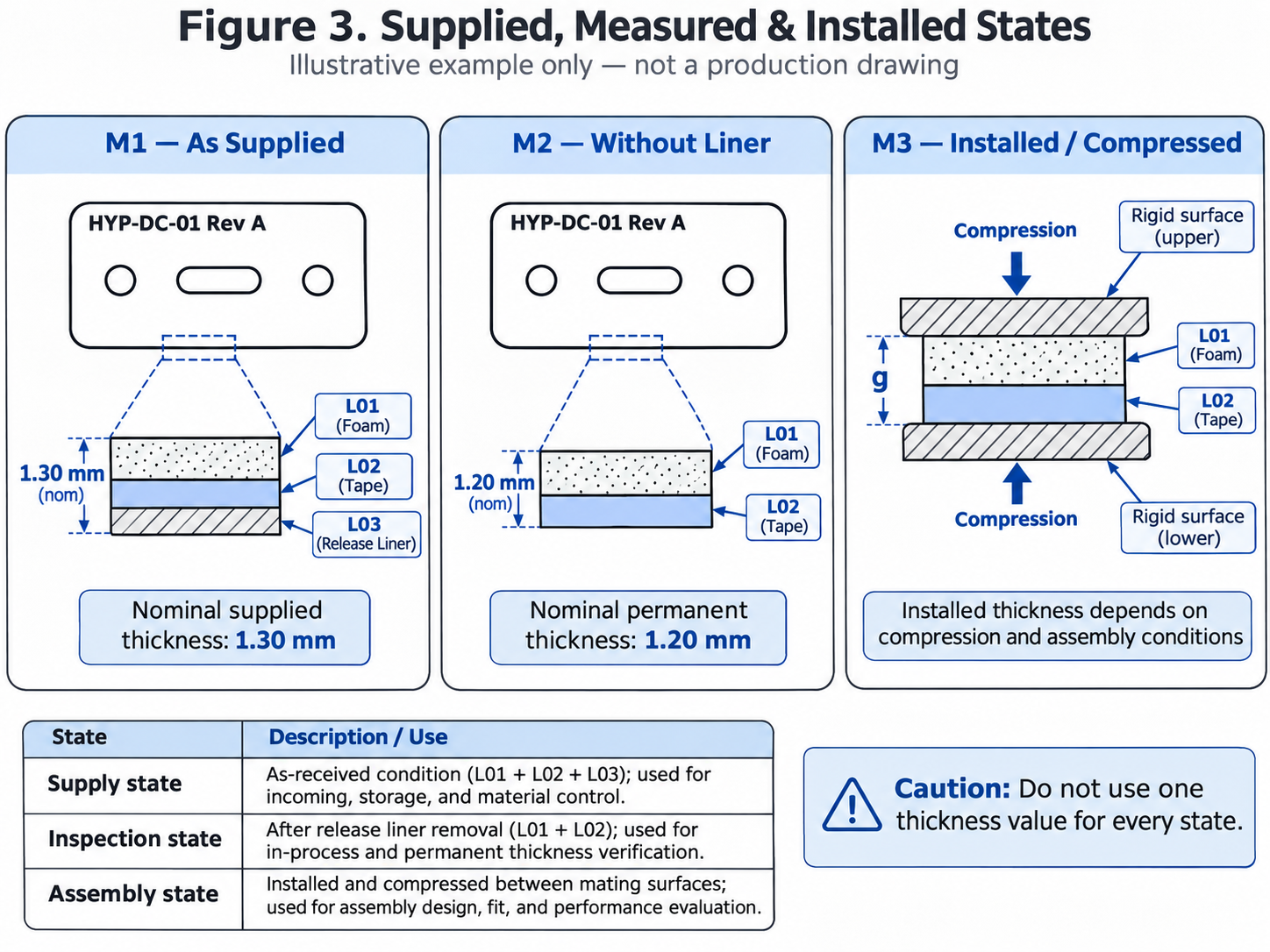
Imagine one report measures the pad with the liner still attached and another measures the foam-and-tape assembly after peeling the liner. Even if both reports state “total thickness,” their results cannot be compared as though they measured the same object. A second disagreement may arise if a compressible foam is measured using different contact conditions. The correct response is to identify the specimen and test basis, not simply choose the more favorable reading.
For geometry and thickness inspection, the project may need to specify relevant support or fixture conditions, contact force or pressure, measurement locations, conditioning or dwell time, and environment. Which of these matters depends on the material and feature; there is no single instrument setting that can be assumed for all flat die-cut parts. Published methods cover different material classes: ISO 1923 addresses linear dimensions of cellular plastics and rubbers, ISO 4593 covers mechanical-scanning thickness of applicable plastic films and sheets, and ASTM D3652/D3652M addresses pressure-sensitive tape thickness [5–7]. Their published scopes are useful for selecting a method to review, but the appropriate edition, procedure and acceptance criteria must be determined for the actual project.
Keep three evidence levels separate. A material technical data sheet describes material properties under its stated methods and conditions. A converted-part inspection checks the particular cut-and-laminated geometry against agreed requirements. An assembly test addresses installed fit or functional performance. A foam manufacturer's compression-force data, for example, cannot by itself establish that a particular assembled pad will meet an unspecified gap, closure-force or sealing requirement [2].
If the project needs first-article inspection, dimensional reports, a sample quantity, or ongoing sampling, define the scope and acceptance basis explicitly. None of these is a universal requirement implied by the word “die-cut.” For the hypothetical pad, the most important unresolved values are the critical feature limits, the actual material grades, the inspection state and the mating gap g. Until those are established, the illustration is not a released inspection drawing.
Use the Checklist at the Right Stage: RFQ, Prototype, and Release
The purpose of the checklist is to resolve the right unknowns at the right time. Requiring every production-level detail before the first conversation can delay a useful feasibility discussion. On the other hand, leaving a material choice or acceptance condition marked “TBD” does not make a prototype self-validating.
| Project stage | What is sufficient to move the discussion forward | What must be resolved before the next commitment |
|---|---|---|
| Initial inquiry | Sketch, current drawing or reference part; intended function; known material/layer information; clearly labeled unknowns | Identify uncertainties that materially affect feasibility, scope or indicative price |
| Comparable RFQ | Controlled part version, nominal geometry, provisional or specified material construction, quantities and delivery basis; quote assumptions stated | Make exclusions and any proposed material or construction alternatives visible so quotes are comparable |
| Prototype authorization and review | Identified sample revision, actual material/layer configuration, critical interfaces and purpose of the sample | Agree what the sample is intended to prove and how open critical requirements will be evaluated |
| Production release | Controlled geometry and material specifications, agreed cut/liner/delivery outcome, applicable inspection method and acceptance criteria | Resolve or formally disposition remaining deviations before using the specification for production acceptance |
Swipe horizontally to view all columns.
For HYP-DC-01, a sketch with the 48.0 × 28.0 mm outline, holes, slot and preliminary three-layer construction is enough to begin a technical conversation. It is not yet sufficient for formal sample approval: the foam and tape grades are unspecified, no functional tolerances have been allocated, the measurement conditions remain open, and the installed gap is unknown. Those are identifiable decisions, not paperwork for its own sake.
The final practical check is whether the same drawing revision, layer definition and measurement basis would lead the design engineer, purchasing team, converter and receiving inspector to evaluate the same part. If not, document the specific disagreement before relying on a quote or interpreting the sample result.
You can send the drawing or sketch you have, your intended assembly function and any unresolved layer or fit questions through the TC Precision Components request-for-quote page to begin a project-specific discussion. An initial inquiry does not imply that a particular tolerance, material alternative, inspection plan or converting route has been approved.
Technical references
The references below support general drawing, material-construction and measurement distinctions. A source's published scope or typical material data is not a project specification or a TC Precision Components qualification record.
- ASME — Dimensioning and Tolerancing (Y14.5), official scope; related drawing practices and revision guidance are covered by the ASME Y14 family. The proprietary standard clauses were not reproduced or relied on for numeric requirements.
- Rogers — PORON 4701-40 product family, grade-specific material thickness and compression-data context, not converted-part tolerances.
- 3M — Double Coated Tape 9495LE, Technical Data Sheet, September 2024, p. 1 construction and representative thickness values.
- tesa — Converting Capabilities, published examples of distinct converted-layer and liner presentation options.
- ISO 1923:1981 — Cellular plastics and rubbers, determination of linear dimensions, official scope.
- ISO 4593:1993 — Plastics: Film and sheeting, determination of thickness by mechanical scanning, official scope; embossed film excluded from its stated application.
- ASTM D3652/D3652M-01(2020) — Thickness of Pressure-Sensitive Tapes, official scope.