
Custom Die Cutting & Converting Services
Examine the converting route—from precision cutting to lamination and project-specific verification—against your material, geometry and drawing requirements.

From material to functional component.
Custom die cutting starts with the material, drawing and assembly requirements. The manufacturing route may include adhesive lamination, precision cutting and project-specific inspection, depending on the component construction.
- 01Material
- 02Lamination / Bonding
- 03Precision Die Cutting
- 04Verification
- 05Functional Component
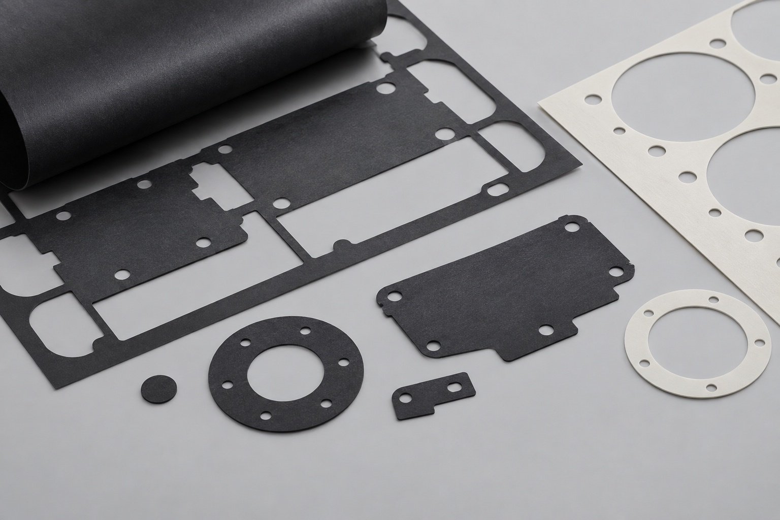
Precision Die Cutting
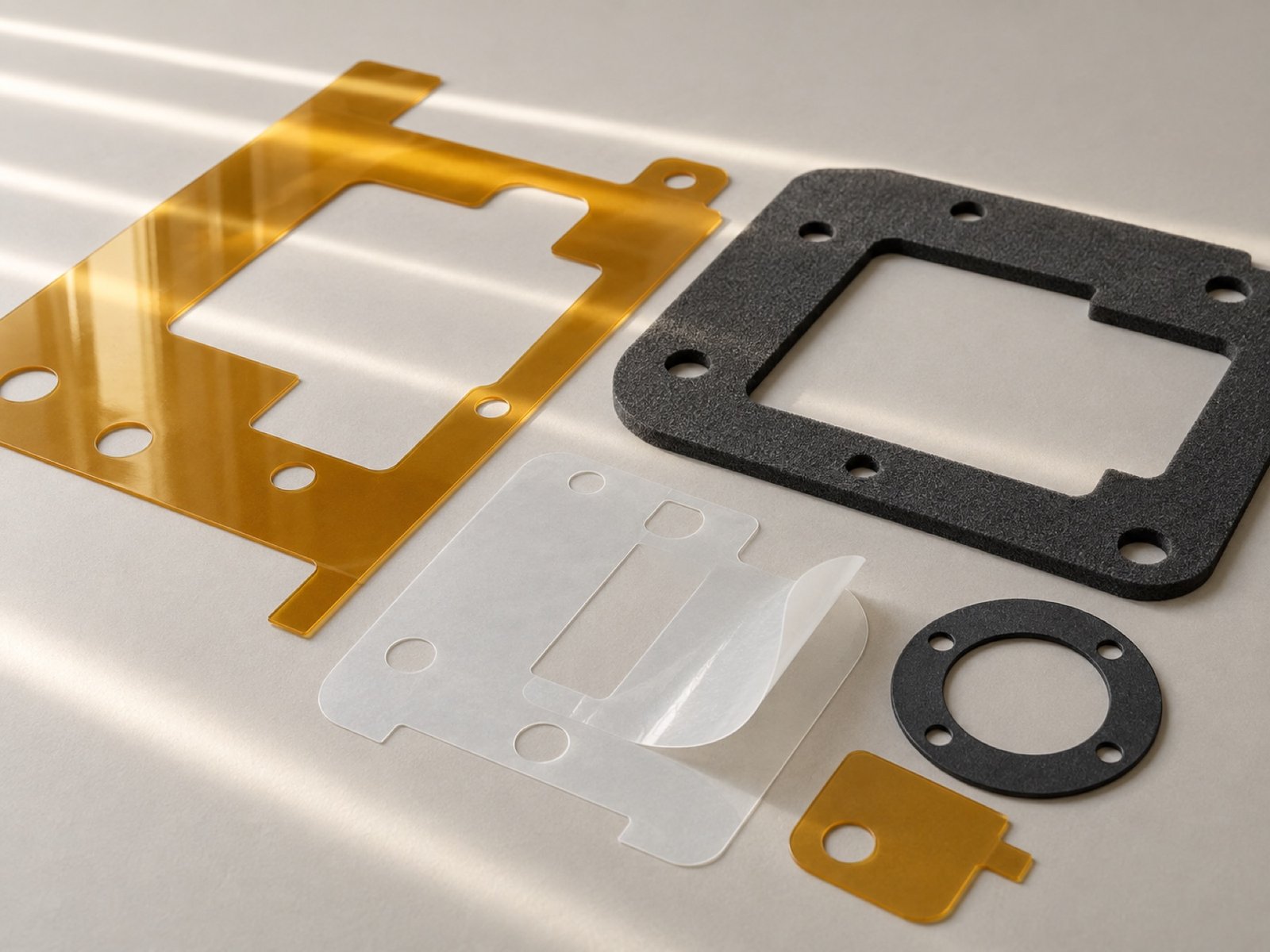
Precision die cutting forms drawing-defined profiles, holes and cutouts in suitable flexible sheet materials. Material thickness, critical feature size, required tolerances and part-handling format guide the cutting method.
- Custom profiles and openings
- Thin and flexible materials
- Parts shaped for functional fit
Lamination & Bonding
Adhesive lamination can combine compatible films, foams and functional layers into multi-layer die-cut parts. Bonding surfaces, adhesive type, layer sequence, total thickness and release-liner requirements guide the construction.
- Adhesive and liner constructions
- Foam and film lamination
- Multi-material structures
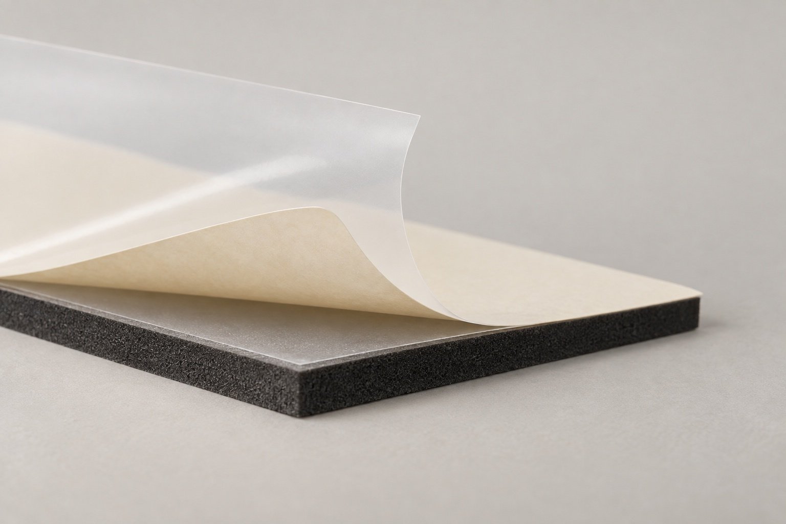
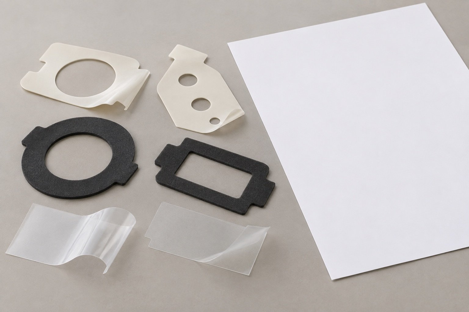
Prototyping & Low-Volume Production
Prototypes can help evaluate part geometry, material selection, layer construction and assembly fit before production. Tooling, sample quantities and validation requirements are reviewed for each project.
Explore Precision Die Cutting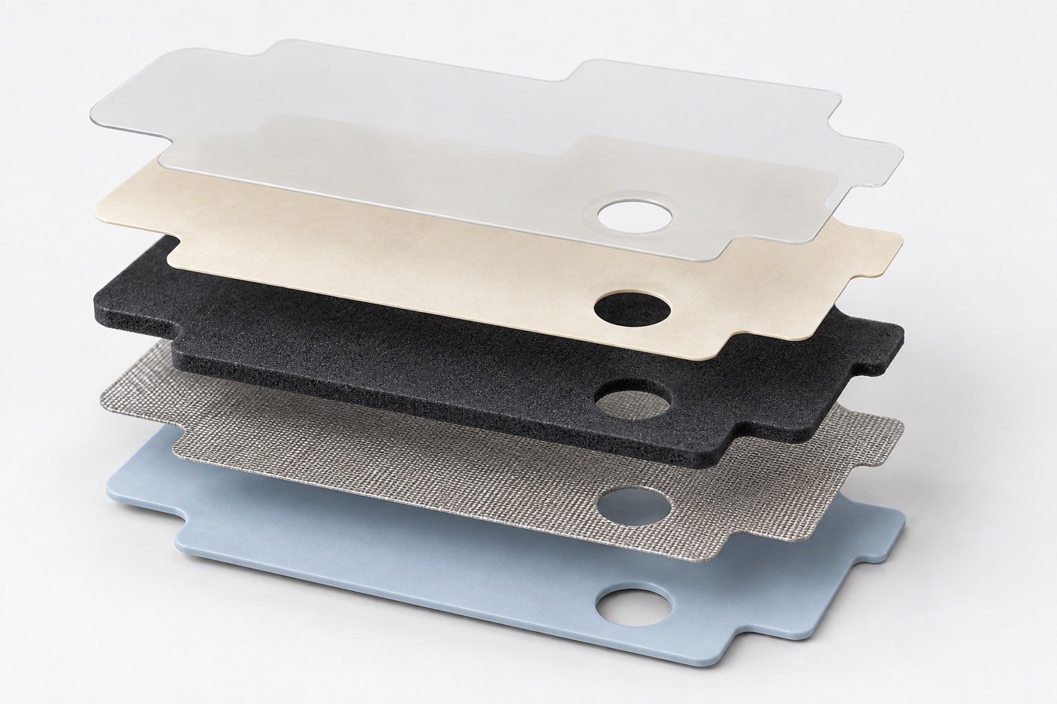
Multi-Layer Die-Cut Assemblies
Multi-layer die-cut parts may combine suitable films, foams, adhesives, shielding or thermal materials. Define the layer order, total thickness, adhesive side, cutting depth and liner requirements before confirming the construction.
Explore Lamination & BondingQuality & Tolerance Control
Inspection requirements are defined from the approved drawing, material construction and critical features. Dimensional checks, cut-edge condition, layer alignment and documentation scope are agreed according to the component.
Drawing & material review
Review drawing revision, material grade, layer structure, critical dimensions and acceptance criteria.
In-process checks
Check specified dimensions, cut edges or layer alignment at agreed production stages.
Final verification
Review finished-part dimensions, appearance and any agreed inspection records before release.
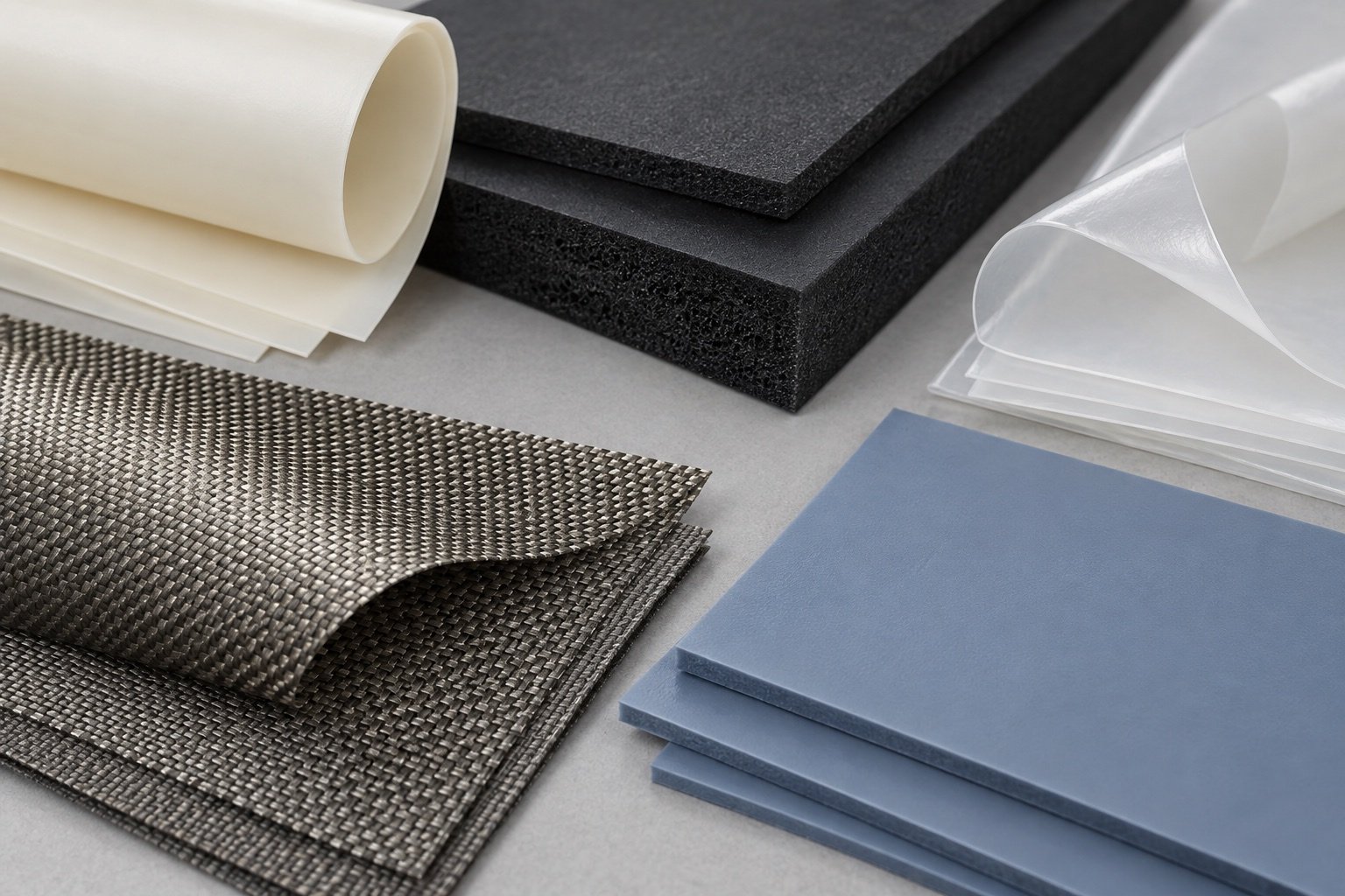
Capabilities across flexible material families.
Material grade and construction influence the converting method. Review thickness, flexibility, compressibility, bonding surfaces and electrical, shielding or thermal requirements before selecting the process.
Explore MaterialsA clear route from requirements to verification.
A drawing or sample, required function, material specification and estimated quantity provide the starting point. These inputs guide feasibility, sampling, production planning and inspection requirements.
- 01
Requirements
Drawing revision, function, dimensions, critical tolerances and quantity.
- 02
Material / Structure Review
Material grade, thickness, layer sequence and adhesive or liner needs.
- 03
Prototype if Needed
Assess material, geometry, fit and handling where samples are required.
- 04
Production
Manufacture to the approved drawing and agreed construction.
- 05
Verification
Review specified dimensions, appearance and required inspection records.
Questions about our converting capabilities.
Practical answers for engineering and purchasing teams.
What custom die-cutting and converting services do you support?
Our project scope covers precision die cutting, lamination and bonding, adhesive-backed constructions, and project-specific prototype and verification requirements. These processes can turn flexible sheet materials into drawing-defined functional components. The appropriate manufacturing route is reviewed against material behavior, geometry, layer construction, assembly needs and production volume.
What flexible materials can be precision die cut or converted?
Material families under review include electrical insulation films, foam, rubber, silicone sheets, pressure-sensitive adhesive constructions, conductive shielding materials and thermal interface sheets. Converting feasibility depends on the specified grade, thickness, flexibility, surface properties and part geometry. Not every material or grade is suitable for every process.
How is the right die-cutting process selected for a custom component?
Process selection depends on material thickness, geometry, critical features, sheet or roll format, layer construction and order volume. Rotary and flatbed cutting may be evaluated for different production requirements, while kiss cutting controls cut depth when a release liner must remain intact. The final route should be confirmed after reviewing the complete part specification.
Can adhesive, foam and film layers be combined into one custom die-cut component?
Compatible adhesive layers, foams, films and other specified functional materials can be evaluated for laminated die-cut constructions. The design should define layer order, bonding surfaces, adhesive placement, total thickness and which layers must be cut. Material compatibility and alignment requirements should be reviewed before confirming the converting process.
Can you manufacture custom die-cut parts with small holes, narrow features and complex profiles?
Custom holes, slots, internal cutouts and narrow features can be evaluated from drawings or samples. Feasibility depends on material behavior, thickness, feature spacing, edge requirements and critical tolerances. An early design-for-manufacturability (DFM) review helps identify potential cutting, handling or dimensional issues before tooling and production.
Can die-cut parts be supplied on release liners, sheets or rolls for assembly?
Delivery formats can be evaluated according to the material, liner construction and assembly process. Kiss-cut adhesive parts may remain on a release liner, while sheet-based or roll-based presentation may be considered when the process supports it. Specify part orientation, spacing, liner removal and handling requirements before confirming the production and delivery format.
Do you support prototyping and low-volume production before regular manufacturing?
Prototype and low-volume requirements can be evaluated before a regular production route is finalized. Samples may help verify material suitability, dimensional fit, layer construction and assembly handling. Feasibility, tooling requirements, costs and lead times depend on the part design, selected material and required quantities.
How are die-cutting tolerances and quality requirements controlled?
Critical dimensions and acceptance criteria should be defined from the approved drawing and functional requirements. Achievable tolerances depend on material thickness, flexibility, geometry and the selected process. Depending on the project, verification may include first-article, in-process and final checks of dimensions, cut quality and layer construction. Inspection records should be agreed before production.
What determines tooling cost, minimum order quantity and lead time for custom die-cut parts?
These requirements depend on material availability, part geometry, tooling complexity, layer construction, order volume and inspection needs. A prototype project may have different cost and scheduling considerations from repeat production. Share your trial quantity, expected production volume and target delivery schedule so feasible options can be evaluated before quotation.
What information should I provide for a custom die-cutting or converting quotation?
Send a drawing or reference sample, part function, dimensions, critical tolerances, material grade and thickness if known, and estimated quantities. Include layer construction, adhesive or liner needs, operating conditions, assembly requirements and any required inspection documentation. If the specification is incomplete, describe the application so the missing details can be identified during review.
Need a Custom Die-Cut or Laminated Component?
Send us your drawing, material requirements, dimensions and estimated quantity for review.