APPLICATION 01 / 06 · POWER ELECTRONICS
Functional Components for Power Electronics & Power Supplies
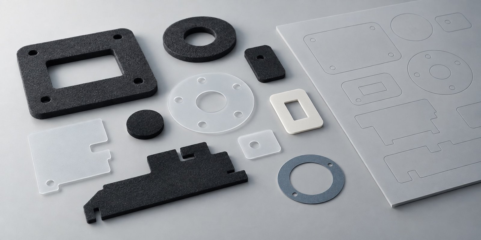
Custom die-cut insulation, thermal, shielding and bonding parts for the interfaces inside power-conversion and power-supply assemblies.
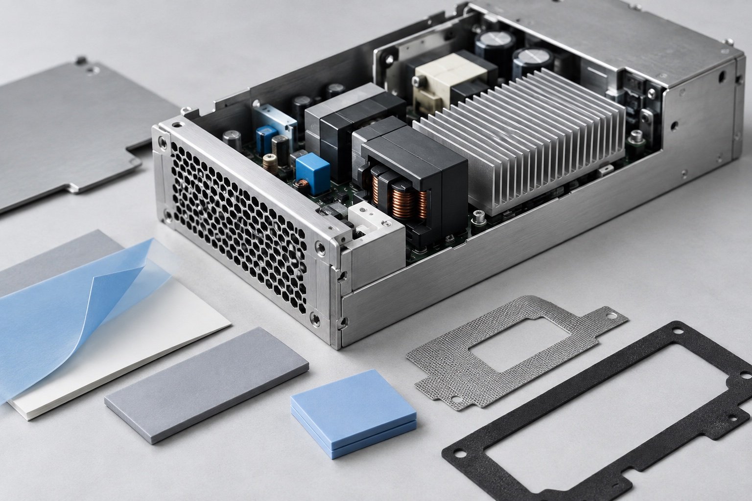
APPLICATION OVERVIEW
The interface inside the power assembly matters.
Power supplies and conversion assemblies bring electrical, thermal and mechanical interfaces into a compact space. A functional layer may separate conductors, manage heat transfer or help shield an enclosure opening.
The component is defined around the assembly drawing, contact surfaces and service conditions—not by a generic catalogue shape. TC focuses on converted functional materials, not semiconductors or complete power equipment.
FUNCTIONAL REQUIREMENTS
Five functions. One assembly context.
The same power assembly may need several distinct material functions at different interfaces.
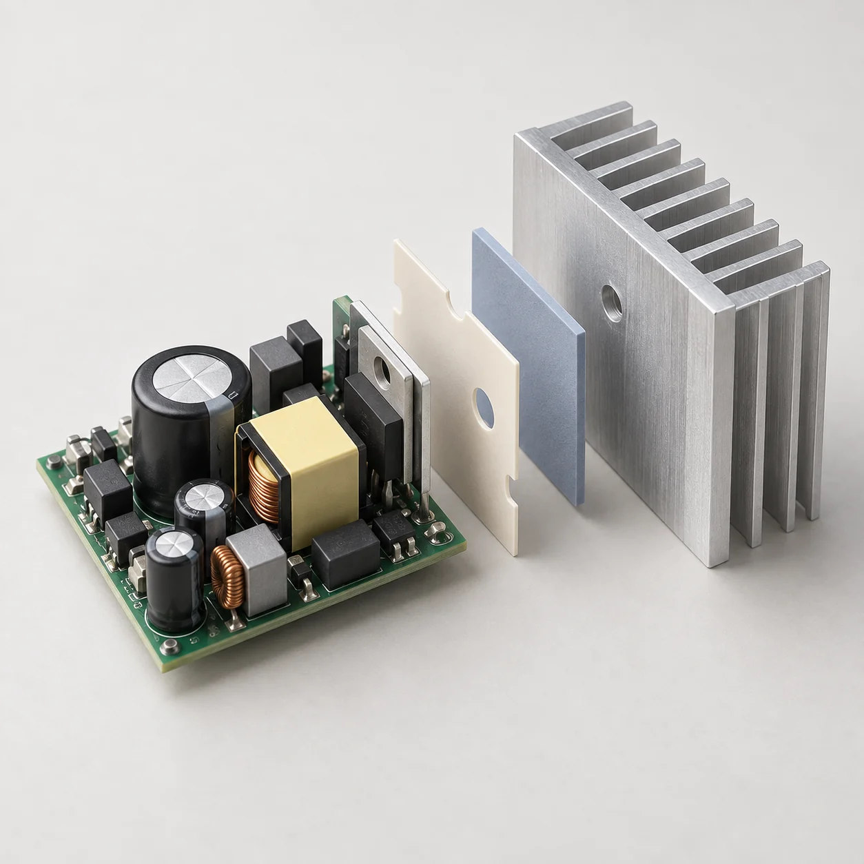
Electrical insulation
Film or sheet barriers can separate conductive regions where the design calls for isolation.
Thermal management
A die-cut thermal interface can be shaped around the available contact area and compression path.
EMI shielding
Conductive or shielding forms can be reviewed where enclosure contact and interference control matter.
Adhesive bonding
Adhesive-backed layers can hold functional films or pads in a defined assembly position.
Cushioning and spacing
Compliant shapes may help maintain clearance or protect a local contact point.
COMPONENT SOLUTIONS
Component routes for power equipment.
Each family is chosen for a specific location and function within the power assembly.
Electrical Insulation Components
Custom film and sheet shapes for electrical separation and localized barriers.
Explore component →Thermal Management Components
Cut thermal interface forms for a defined heat-transfer contact area.
Explore component →EMI Shielding & Magnetic Shielding Components
Shielding forms considered around conductive paths and enclosure contact.
Explore component →Adhesive Functional Components
Adhesive functional layers for positioning or joining material surfaces.
Explore component →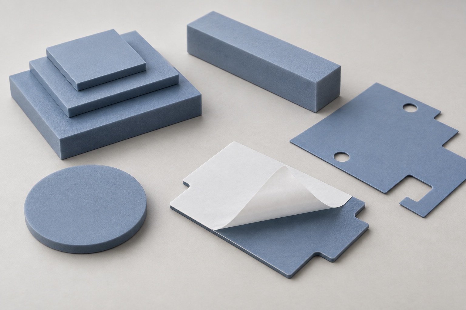
MATERIAL OPTIONS
Select the material around the interface.
Material choice depends on the electrical, thermal and assembly requirement rather than a single preferred sheet.
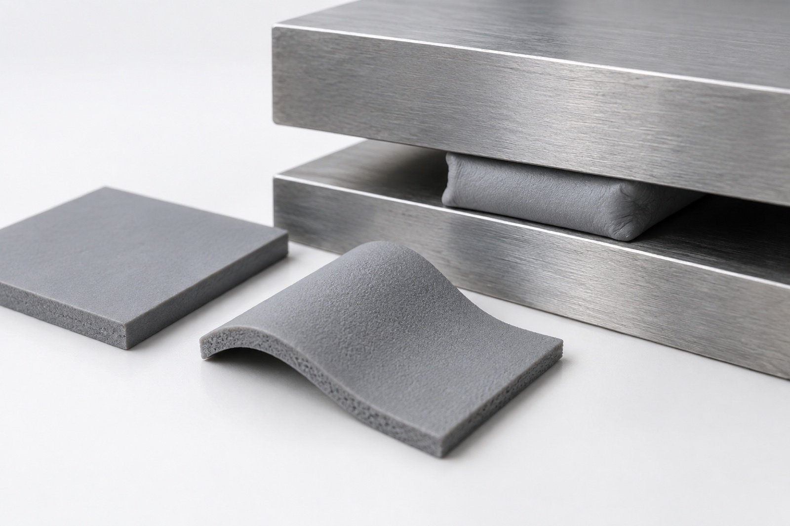
Insulation Materials
Film and sheet families for electrical isolation and protective barriers.
Explore material →Thermal Management Materials
Thermal sheet options considered against contact geometry and heat-transfer needs.
Explore material →Conductive & Shielding Materials
Conductive and shielding materials reviewed where contact and EMI requirements apply.
Explore material →Adhesive Materials
Adhesive materials for bonding or locating a functional layer in the assembly.
Explore material →ENGINEERING CONSIDERATIONS
Define the critical interfaces first.
The drawing and operating context determine what needs to be checked before a construction is selected.
Electrical separation
Identify exposed conductors, clearance areas and the location of each insulating barrier.
Thermal contact
Review contact area, gap and compression so a thermal layer fits its intended interface.
Shielding contact
Confirm where conductive continuity is needed and where it must be avoided.
Assembly geometry
Account for openings, cutouts, thickness and adhesive placement on the customer drawing.
MANUFACTURING CAPABILITIES
Converting steps that support the design.
The required construction determines the die-cutting and lamination route.
Precision Die Cutting
Shape thin films, thermal sheets and shielding materials to drawing-defined profiles.
Explore capability →Lamination & Bonding
Combine functional layers or adhesive backing when the assembly requires it.
Explore capability →Quality & Tolerance Control
Review drawing requirements and project-specific dimensional checkpoints.
Explore capability →QUALITY & VERIFICATION
Verification follows the drawing.
For power-equipment parts, review focuses on the specified material, cut geometry and relevant interfaces. The verification plan is defined for each project.
- Drawing review
- Material confirmation
- Dimensional inspection
- Visual inspection
- Project-specific verification
RELATED PAGES
Continue from the equipment context.
Compare another application, or return to the full application overview.
FAQ
Power electronics questions, answered.
Practical questions about this equipment application and its functional components.
What types of die-cut parts are used in power supplies?
A power-supply assembly may require insulation films, thermal interface pads, shielding forms, adhesive layers or spacing parts. The appropriate shape depends on the equipment drawing and function.
Can insulation materials be cut around connectors and mounting points?
Yes. Openings and profiles can be reviewed against the drawing, sheet material and required assembly clearances.
How is a thermal interface component specified?
Start with the contact surfaces, gap, expected compression and available geometry. Material selection and cut profile are then reviewed for that interface.
Can shielding and insulation appear in the same assembly?
They can serve different locations or functions. The drawing should identify where conductive contact is intended and where electrical isolation is required.
Can adhesive backing be added to a functional layer?
An adhesive-backed or laminated construction can be considered when it supports positioning or bonding in the assembly. The construction is reviewed per project.
What should I send for a power-electronics quotation?
Send the component drawing or sample, assembly location, functional requirements, material specification if available and estimated quantity.
START A PROJECT
Have a Power Electronics Component Project?
Send us your drawing, functional requirements, material specification if available and estimated quantity for review.
Request a Quote →