REQUIREMENTS TO VERIFICATION
Quality & Tolerance Control
Quality starts with the drawing, material specification and agreed project requirements. Dimensional, visual and production-stage checks are planned around the features that matter to the assembly.
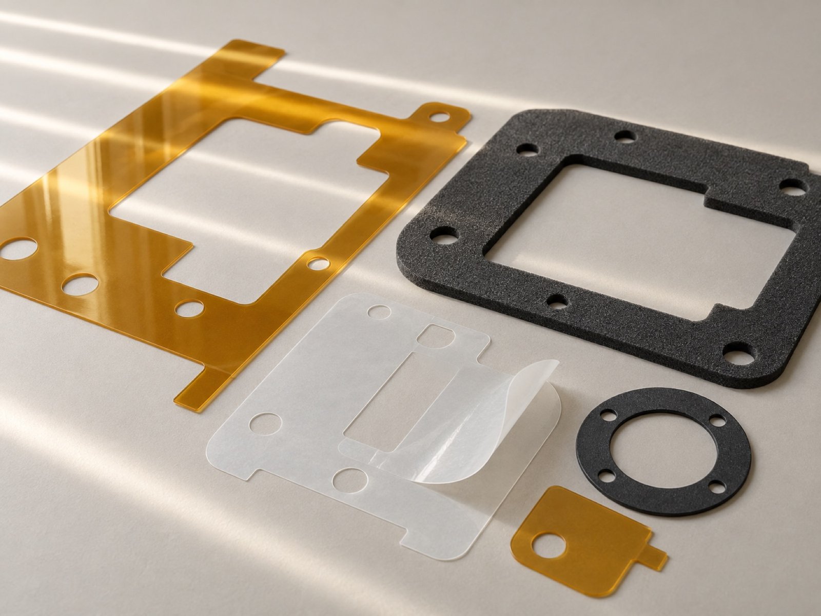
DEFINE THE STANDARD
Quality Starts with the Requirement
Inspection only has meaning when the component’s intended function and acceptance criteria are clear from the start.
Drawing & geometry
Identify dimensions, critical features and assembly interfaces.
Material & construction
Confirm material, thickness, adhesive or layered requirements.
Agreed acceptance
Define which characteristics need verification and how they will be judged.
Agreed requirements guide the checks.
TOLERANCE CONTROL
Die Cutting Tolerances
Die cutting tolerances are reviewed for each component—not assumed from a single number or material family.
The workable tolerance follows the part.
Material behavior, thickness, geometry, feature size and process route affect what can be held. Critical die cut tolerances should be identified on the drawing and assessed against the intended assembly.
Standard die cutting tolerances are not universal across flexible materials. Tight tolerance die cutting calls for a project-specific review of the critical features and verification method.
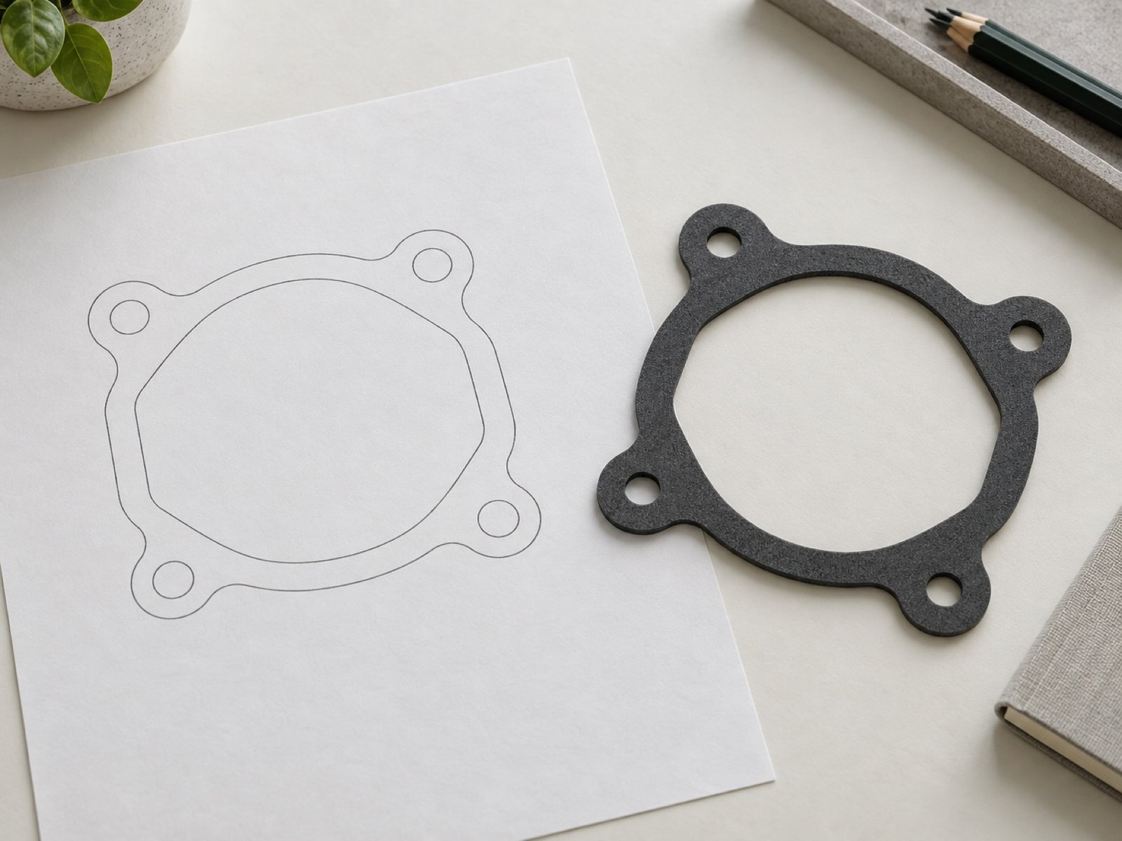
BEFORE PRODUCTION
Drawing & Specification Review
The drawing is the reference for dimensions and critical features. Material, thickness, tolerance, adhesive or liner needs, and functional requirements should be clarified before inspection criteria are set.
INITIAL VERIFICATION
First Article Verification
For a project requiring first article inspection, the first representative part can be checked against the agreed drawing and construction before routine production.
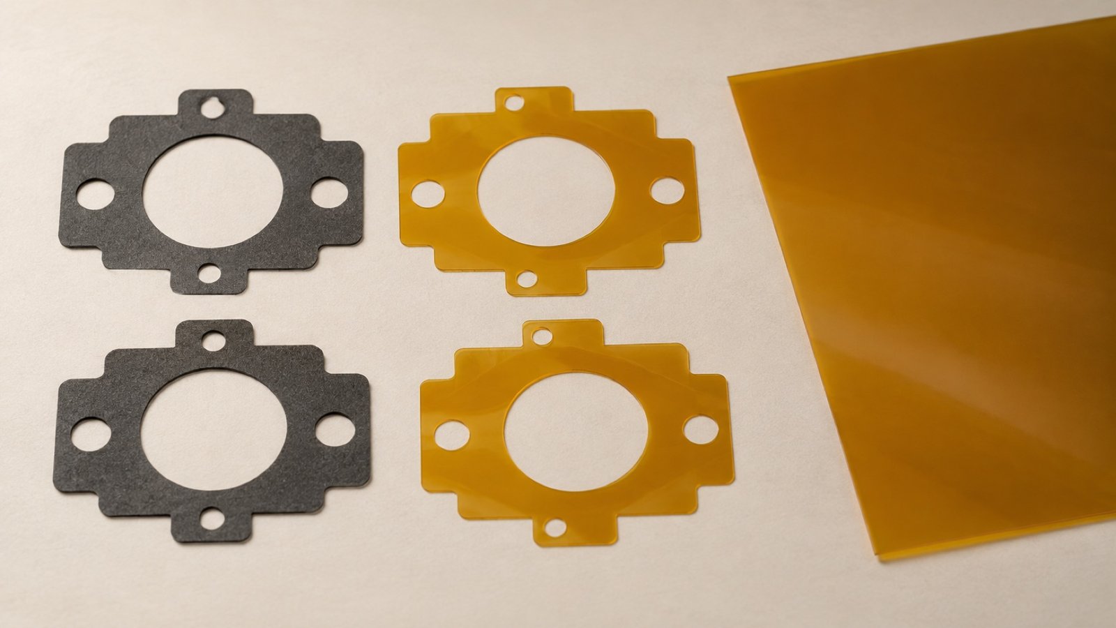
Dimensions
Review the critical profile, openings and specified features.
Material & appearance
Check the agreed material or layer construction and visible condition.
Fit where relevant
Consider the assembly interface against customer-approved requirements.
DURING PRODUCTION
In-Process Inspection
Project-specific checkpoints help compare parts with the approved requirements as production continues.
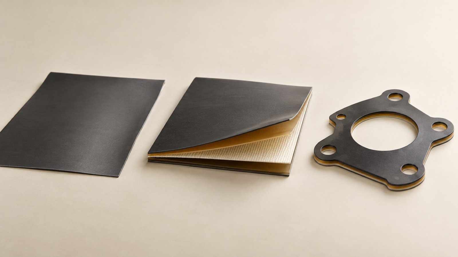
Critical features
Check dimensions or profiles identified as important to fit and function.
Visual condition
Review visible cut edges, surfaces and other specified conditions.
Material & layers
Confirm the material or multi-layer construction at agreed stages.
BEFORE RELEASE
Final Inspection
Before a component is released, the final checks should address the drawing, specification and agreed acceptance criteria. The scope may include critical dimensions, visual condition and construction where these have been defined for the project.
Share Your Inspection Requirements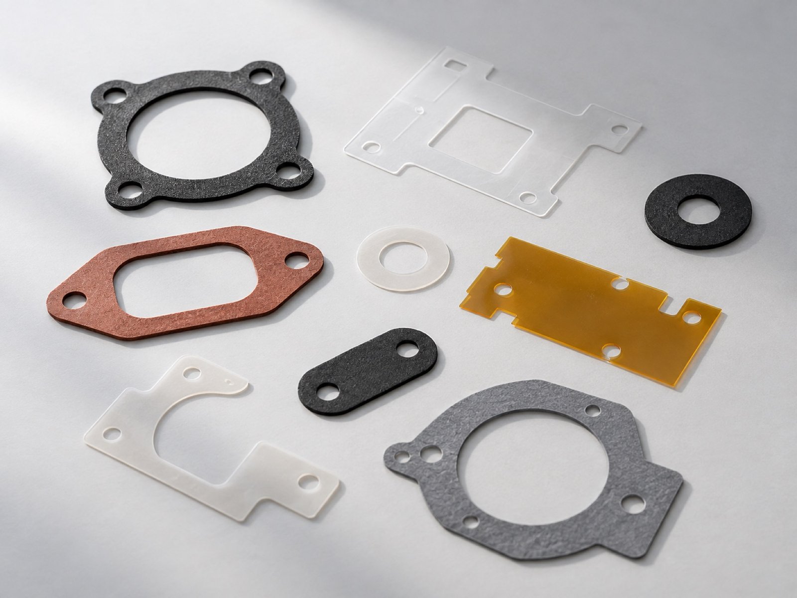
METHOD BY REQUIREMENT
Inspection & Measurement
Dimensional and visual inspection methods are selected according to the component, critical feature and agreed project requirement.
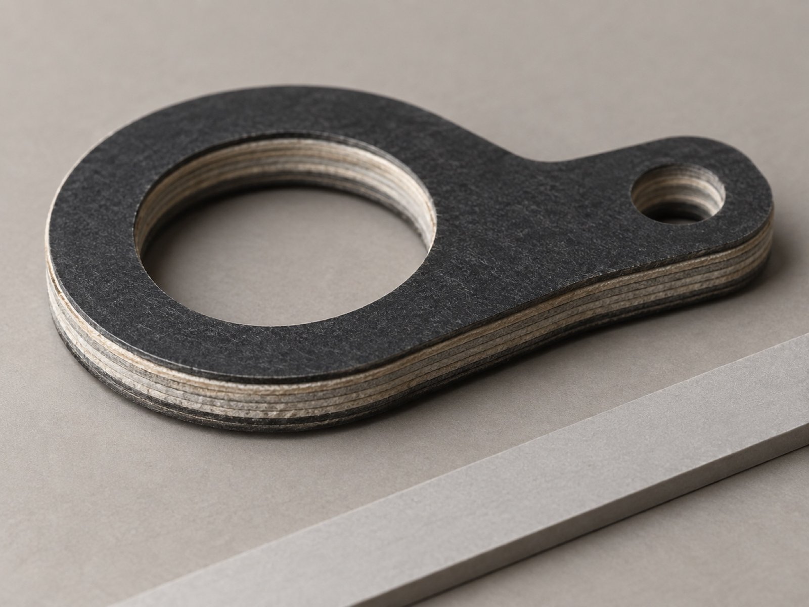
Dimensional review
Assess the specified profile, opening, thickness or other critical dimensions.
Visual review
Examine the appearance and condition relevant to the component function.
Method selection
Confirm the appropriate check and acceptance method for the project.
PROJECT DOCUMENTATION
Documentation & Traceability
Documentation needs vary by project. Inspection records, material references or part identification may be maintained when they are agreed as part of the requirements. The available scope should be confirmed before quoting.
Which checked features should be recorded?
What material information is needed?
What identification is required for the assembly?
FAQ
Quality & Tolerance FAQs
Answers for drawings, inspection criteria and project planning.
What die cutting tolerances can you achieve?
There is no single tolerance that applies to every part. Material, thickness, geometry and critical features are reviewed against the project drawing before a feasible requirement is confirmed.
How are die-cut parts inspected?
Checks are defined around the drawing and agreed requirements. They may include dimensional review, visual condition and material or layer construction, depending on the part.
Do you perform first article inspection?
First article verification can be specified for a project. Share the characteristics and any customer approval needs so the review scope can be confirmed before production.
How are critical dimensions controlled?
Critical dimensions should be identified on the drawing. The inspection method and checkpoints are then planned around the material, feature and agreed acceptance criteria.
Can inspection requirements be defined from customer drawings?
Yes. A drawing, material specification and notes on function or assembly help establish which dimensions and conditions need verification.
How do you verify multi-layer components?
The agreed layer construction, material interfaces and critical dimensions can be reviewed alongside visual condition and the finished die-cut geometry.
Can quality records be provided?
Please include the record type and required details with your RFQ. Availability and scope of project-specific documentation can then be confirmed before quoting.
What should a drawing include for tolerance control?
Include overall dimensions, critical features, material and thickness, relevant tolerances, layer or adhesive requirements and the intended assembly interface.
START A PROJECT
Have a Component with Critical Tolerance Requirements?
Send us your drawing, material, dimensions and critical tolerance requirements for review.
Request a Quote