
Thermal Management Components
Custom die-cut thermal gap pads and interface components for electronic and industrial assemblies. Material selection and part geometry are reviewed against the heat-transfer path, installed gap, contact surfaces, compression and electrical requirements.

Heat-Transfer Interface
SOURCE · CONTACT · HEAT PATH
Gap Filling
GAP RANGE · MATERIAL COMPLIANCE
Surface Contact
COMPRESSION · ASSEMBLY FIT

Die-Cut Thermal Pads for Contact and Gap Fit
Custom thermal interface parts may include gap pads, sheets, frames and drawing-defined profiles with holes or cutouts. The selected material must suit the heat-transfer path, installed gap, contact pressure and operating environment. Part geometry and any adhesive or liner construction should be reviewed alongside the material specification.
Materials We Convert
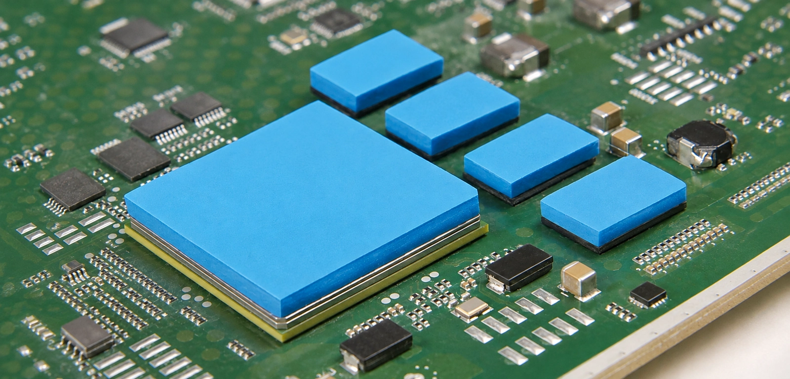
Thermal Interface Sheets
Sheet-form thermal interface materials are reviewed for contact conditions, thickness, electrical properties and the required heat-transfer direction.

Silicone Thermal Sheets
Compliant silicone-based thermal sheets require grade-specific review of thermal properties, compression behavior and operating temperature.

Thermal Gap Sheets
Flexible gap-filling sheets are evaluated against the assembled gap range, surface variation and available compression force.

Die-Cut Thermal Sheets
Custom profiles, holes and cutouts are defined after selecting a suitable thermal sheet grade, thickness and handling method.
Engineering
Considerations
Gap & Thickness
Define the minimum and maximum installed gap, selected sheet thickness and dimensional variation.
Contact & Compression
Review mating surfaces, available assembly force and material-specific compression behavior.
Geometry & Placement
Specify contact area, cutouts, critical edges, electrical clearance and any adhesive or liner needs.

How We Manufacture Them

Precision Die Cutting
Review pad outlines, holes, narrow features and cut-edge conditions against material thickness and softness.
Lamination & Bonding
Evaluate compatible adhesive, support-film and liner constructions where positioning or assembly requires them.
Quality & Tolerance Control
Define checks for material identity, thickness, profile dimensions and backing alignment against the approved drawing.
Thermal Component FAQs
Answers about gap pads, contact, material and project input.
What is a thermal gap pad, and where is it used?
A thermal gap pad is a preformed, typically compliant thermal interface material used between a heat-generating component and a heat sink, chassis or another receiving surface. It helps bridge an intended gap and improve contact between mating surfaces. Material grade, thickness, compression and electrical requirements must be selected for the specific assembly.
How do I choose the right thickness for a thermal gap pad?
Start with the minimum and maximum installed gap, dimensional tolerances, mating-surface conditions and available compression force. A pad selected only from the nominal gap may provide insufficient contact or excessive loading. The appropriate thickness and compression range should be checked against the selected material grade and the actual assembly.
Does higher thermal conductivity always mean better thermal performance?
No. Thermal conductivity, usually expressed in W/m·K, is a material property. Installed thermal resistance also depends on pad thickness, compression, surface contact and test conditions. Compare material data under relevant operating conditions and validate the complete thermal interface before assuming that a higher conductivity rating will improve cooling.
How does compression affect thermal gap pad performance?
Compression helps a compliant thermal pad conform to mating surfaces and maintain contact across the interface. Insufficient compression may leave gaps, while excessive compression can place unwanted stress on components or circuit boards. The suitable compression range depends on the material grade, gap variation and available assembly force. Material-specific data should guide the selection.
Can thermal interface pads provide both heat transfer and electrical insulation?
Some thermal interface materials are designed to conduct heat while providing electrical insulation, but others may be electrically conductive. Review grade-specific dielectric properties, thickness, resistivity and operating conditions. Electrical insulation of the complete assembly must be validated against the applicable design and safety requirements, not assumed from a thermal pad’s published material data. For separate barrier and spacer functions, see electrical insulation components; these are not a substitute for a qualified thermal interface material.
Can thermal interface sheets be die cut into custom shapes with holes and cutouts?
Custom thermal pad shapes, holes, slots and other profiles can be evaluated from drawings or samples. Die-cutting suitability depends on material thickness, softness, tackiness, feature spacing and handling requirements. Identify critical dimensions, required cut-edge conditions and any liner or carrier construction before confirming the manufacturing approach.
Can custom thermal pads include adhesive backing or release liners?
Adhesive backing and release liners may be considered when a thermal pad requires controlled placement during assembly. The selected adhesive must be compatible with the thermal material, mating substrate and operating conditions. Additional layers can affect thermal resistance and electrical properties, so adhesive coverage, thickness, liner handling and application requirements should be reviewed before production. For general placement and backing constructions, see adhesive functional components; thermal compatibility remains project-specific.
How are custom die-cut thermal pads inspected and thermal performance verified?
Dimensional inspection may cover material identification, thickness, cut profile, openings, edge quality and backing alignment against agreed requirements. Thermal conductivity, dielectric properties and compression behavior should be checked using grade-specific supplier documentation where available. Actual interface performance requires appropriate application-level testing and cannot be established by dimensional inspection alone.
Do you support prototype and low-volume custom thermal gap pad orders?
Prototype and low-volume requirements can be evaluated before regular production. Samples can help verify part dimensions, placement and contact fit in the intended assembly. Material availability, tooling costs, minimum quantities and lead times depend on the selected grade, thickness, geometry and anticipated production volume. Functional thermal testing requirements should be agreed separately.
What information is needed to quote custom die-cut thermal gap pads?
Send a drawing or sample, drawing revision, pad dimensions, minimum and maximum installed gap, contact surfaces and estimated quantity for each design. Include material or thickness preferences, thermal targets, operating temperature, electrical insulation requirements, expected compression or assembly force, and adhesive or liner needs. If the material is undecided, describe the heat-transfer problem for an initial review.
Have a Thermal Gap Pad Project?
Share your drawing, installed gap range, contact surfaces, thermal requirements, material preferences and estimated quantity for review.